
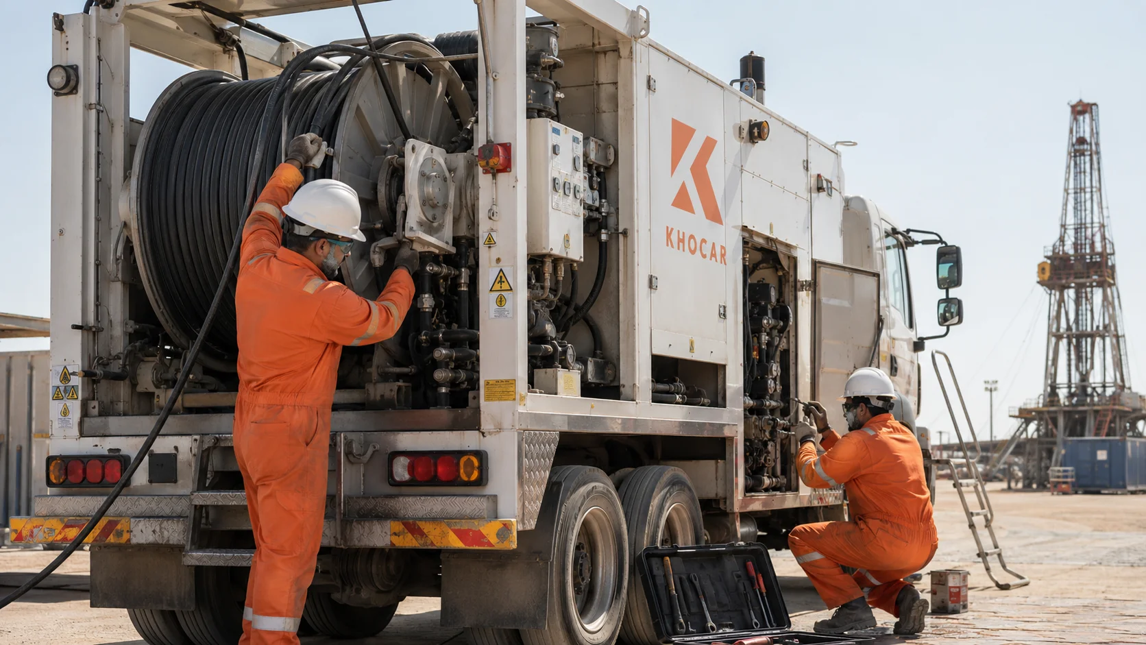
A wireline unit rarely moves from “healthy” to “failed” without giving the crew some warning. The first clue may be a tension value that flickers, a drum that no longer responds smoothly, a hydraulic temperature trend that keeps climbing, or a cable that begins stacking unevenly. Those changes can appear minor at the workshop, yet become serious once the truck or skid is mobilized to a wellsite.
Effective wireline logging unit maintenance is therefore less about waiting for a breakdown and more about recognizing deterioration while the equipment is still safe, accessible and repairable. In Abu Dhabi and across the UAE, high ambient heat, dust, long transport distances, demanding duty cycles and tight project windows can reduce the margin for ignoring small faults.
This guide explains seven practical warning signs, what each one may indicate, how to decide whether the unit should be stopped or scheduled for repair, and what to inspect before the next field job. The goal is simple: protect personnel, preserve measurement quality, and prevent a manageable workshop repair from becoming an expensive field failure.
Key Takeaways
- Changes in depth, tension or line-speed readings can indicate encoder, load-cell, measuring-head, wiring, calibration or mechanical problems. Do not assume the display is wrong until the complete signal path has been checked.
- Jerky winch motion, unstable speed, delayed response or drum creep can point to hydraulic, brake, gearbox, control or mechanical wear that should be corrected before mobilization.
- Rising hydraulic temperature, falling charge pressure, unusual pump noise, foaming fluid or repeated leaks are warning signs, not normal consequences of working in the UAE heat.
- Uneven cable spooling can damage the cable, distort depth measurement and increase the risk of crushing, crossover, birdcaging or localized armor wear.
- Intermittent electrical faults are often more dangerous than complete failures because the unit may pass a brief test and then lose a sensor, alarm, interlock or control signal under vibration and heat.
- A good logging unit preventive maintenance program combines pre-departure checks, daily checks, post-job cleaning and inspection, scheduled servicing, calibration records and trend-based repair decisions.
- Any safety-critical defect involving braking, uncontrolled movement, structural damage, hydraulic hose failure, electrical burning, shutdown circuits or unreliable tension/depth data should be assessed before the unit returns to service.
| The clearest signs a wireline logging unit needs repair are unstable depth or tension data, jerky winch operation, abnormal hydraulic heat or pressure, poor cable spooling, brake or PTO changes, intermittent electrical faults, and increasing leaks, vibration, or structural wear. One symptom may have several causes, so the correct response is a controlled inspection, not parts replacement by guesswork. |
Why Early Warning Signs Matter in Wireline Operations
A wireline logging unit is a connected system. The truck or skid provides the platform and power; the engine and power take-off drive the hydraulic system; pumps and motors control the winch; the brake and transmission control movement; the drum stores and deploys the cable; the measuring head, encoder and load cell generate depth and tension information; and the operator panel turns those signals into usable control data. A defect in one area can affect several others.
For example, a worn measuring wheel may first appear as a depth mismatch. If the crew compensates by repeatedly adjusting the display without correcting the mechanical wear, the data can remain unreliable and the cable can continue to suffer. A clogged hydraulic filter may first show as a differential-pressure indication, then as reduced flow, heat and sluggish response. A loose electrical connector may cause only an occasional display dropout in the yard but become a repeated failure after hours of vibration on the road and at the wellsite.
General industrial evidence supports the value of proactive maintenance, although the figures are not specific to wireline units. The U.S. Department of Energy reports that preventive maintenance programs can produce an estimated 12% to 18% cost saving compared with reactive maintenance. A NIST analysis of manufacturing establishments found that stronger use of predictive maintenance was associated with 15% less downtime, an 87% lower defect rate and 66% less inventory growth caused by unplanned maintenance. The practical lesson for wireline fleets is not that every unit will achieve those exact results; it is that condition monitoring, planned service and accurate records usually cost less than repeated run-to-failure repairs.
What Systems Should a Wireline Maintenance Inspection Cover?
| System | What to Inspect | Failure Consequence |
| Measurement and control | Depth encoder, load cell, measuring head, line-speed signal, panel, alarms, shutdown outputs and data connections | Wrong depth or tension, missed alarms, poor control decisions and unreliable job records |
| Winch and drum | Drum, level wind/spooler, bearings, frame, guards, fasteners, gearbox, brake and controls | Uncontrolled movement, uneven spooling, mechanical damage and cable wear |
| Hydraulic system | Reservoir, fluid, filters, pumps, motors, valves, cooler, hoses, fittings, gauges and pressure indicators | Heat, low power, slow response, contamination, leaks and component failure |
| Cable and measuring head | Cable condition, armor, conductor integrity, sheaves, rollers, wheels, lubrication and alignment | Depth error, tension spikes, damaged cable and tool-retrieval risk |
| Electrical system | Batteries, alternator/generator, wiring, relays, breakers, connectors, sensors, lighting, grounding and emergency shutdown | Intermittent operation, false data, overheating, loss of safety functions and no-start conditions |
| Vehicle/chassis/structure | PTO, engine, transmission, suspension, brakes, tires, body, mounts, welds, cabinets and lifting points | Mobilization failure, unsafe transport, structural movement and site rejection |
| Pneumatic and support systems | Air tanks, regulators, lines, fittings, cabin pressurization or purge systems where fitted | Leaks, poor actuator response, moisture damage and loss of required protective functions |
1. Depth, Tension or Line-Speed Readings Drift, Freeze or Jump
The first warning sign is often visible on the operator panel. Depth may increase when the cable is stationary, freeze while the drum is moving, differ from a known reference, or change in sudden steps. Tension may fail to return near zero when unloaded, fluctuate without a corresponding change in tool movement, or show spikes that the operator cannot explain. Line speed may also appear unstable even though the winch sounds steady.
What May Cause Unstable Readings?
- A worn, contaminated or slipping measuring wheel that is not tracking the cable correctly.
- A damaged encoder, incorrect encoder resolution setting, loose coupling or intermittent encoder wiring.
- A load pin or load cell that has drifted, been overloaded, damaged, incorrectly installed or inadequately calibrated.
- Loose connectors, broken shielding, moisture, corrosion or damaged cables between the sensor and operator panel.
- Mechanical movement in the measuring head, sheaves or mounting structure that changes the load path.
- Incorrect zeroing, calibration or setup values after a software, panel or component change.
- Cable diameter, surface condition or routing that does not match the measuring-head setup.
BenchMark Wireline manuals show why these signals matter: operator panels receive depth from an encoder and tension from a load pin, then pass those values to the acquisition system. The panel may also connect alarms and shutdown functions to those measurements. Therefore, a “display problem” may actually begin in the sensor, mechanical interface, wiring, settings or shutdown circuit—not only in the screen itself.
Why This Warning Sign Should Not Be Ignored
Wireline decisions depend on knowing where the tool is and what load the cable is carrying. An unreliable depth signal can affect correlation and tool placement. An unreliable tension signal can hide drag, sticking, sudden unloading or excessive pull. Even when the downhole tool is operating normally, poor surface data can lead to incorrect decisions.
Example
A unit passes a short yard test, but the tension display intermittently drops to zero when the cable is moved sideways by the spooler. The fault may not be a failed load cell; it could be a damaged cable or loose connector that opens only as the harness flexes. Replacing the display would not solve the problem. A technician should reproduce the fault, inspect the complete circuit, confirm the mechanical installation and perform the model-specific calibration and shutdown tests.
What to Do Before Mobilization
- Compare readings with a known reference or approved test method.
- Inspect measuring wheels, rollers, bearings, cable contact and mounting security.
- Check connectors and harnesses while gently moving them to identify intermittent faults.
- Verify zero, encoder resolution, calibration records and alarm/shutdown tests according to the equipment manual.
- Do not rely on repeated software offsets to conceal a mechanical or electrical problem.
2. Winch and Drum Movement Becomes Jerky, Slow or Inconsistent
A healthy wireline winch should respond predictably to the operator’s controls. The exact speed and feel depend on the unit and job, but a change from the unit’s established baseline is significant. Warning signs include delayed response, speed hunting, surging, jerking at low speed, loss of smooth inching control, drum creep in neutral, unusual vibration, slow pickup under load, or a difference between pulling in and paying out.
Likely Causes
- Low, contaminated, aerated or incorrect hydraulic fluid.
- Restricted filters, suction problems, internal leakage or a damaged pump or motor.
- A control valve, servo, joystick, proportional control or linkage that is sticking or out of adjustment.
- Brake drag, worn brake components, incorrect release pressure or a brake that does not apply evenly.
- Gearbox, chain, coupling, bearing or drum-support wear.
- A PTO or transmission problem that changes available input speed or torque.
- An electrical control signal that drops out under vibration, heat or load.
Modern wireline units are designed around controlled conveyance. NOV, for example, describes wireline winches with closed-loop hydraulic systems, fail-safe braking and configurations ranging from slickline to multi-conductor logging cable. Those features depend on the hydraulic, mechanical and control systems operating together. Smooth low-speed control can deteriorate long before the unit loses all movement.
Example
A winch runs normally when cold but begins surging after 40 minutes. The operator notices that hydraulic temperature is rising and low-speed control is becoming difficult. Possible causes include fluid viscosity changing with temperature, internal leakage increasing as components warm, a restricted cooler, a valve problem or a filter restriction. The repair process should measure pressures and temperatures under controlled conditions and compare them with the correct OEM procedure—not simply replace the pump because the winch feels weak.
When to Stop the Unit
Remove the unit from service when movement is uncontrolled, the drum creeps despite the control being neutral, the brake cannot hold as required, the operator cannot maintain predictable speed, or abnormal vibration suggests a mechanical component may fail. These conditions affect both equipment protection and personnel safety.
3. Hydraulic Temperature Rises, Pressure Falls or the System Becomes Noisy
Hydraulics are central to most wireline logging units. Heat and noise are therefore valuable diagnostic clues. A system that consistently runs hotter than its historical baseline, takes longer to develop pressure, loses performance as it warms, produces whining or cavitation sounds, foams the oil, or repeatedly pushes fluid from breathers needs attention.
Common Hydraulic Warning Signs
| Observed Change | Possible Causes to Investigate |
| Temperature rises faster than usual | Low oil level, blocked cooler, dirty airflow path, excessive bypass, internal leakage, wrong viscosity, high load or restricted flow |
| Pressure is slow to build | Pump wear, suction restriction, air ingress, relief-valve issue, low engine/PTO speed or contaminated fluid |
| Pump whines or rattles | Cavitation, aeration, low reservoir level, restricted suction line, incorrect fluid or inlet leak |
| Filter indicator repeatedly shows restriction | Loaded filter, cold/high-viscosity fluid, contamination event or wrong filter element |
| Hoses jump or vibrate | Pressure pulsation, air in the system, loose clamps, unstable valve action or hose deterioration |
| Repeated seal and hose leaks | Excess heat, pressure spikes, incompatible parts, contamination, poor routing or aged materials |
One manufacturer’s logging-unit manual requires daily checks of hydraulic fluid level and differential-pressure indicators, and it separates maintenance into pre-departure, daily, post-job and operating-hour intervals. It also warns that contamination and unsuitable fluid during oil changes can cause serious errors. Those details illustrate a broader rule: hydraulic maintenance is not only about changing oil. Cleanliness, correct fluid, filtration, cooling, pressure checks, hose condition and accurate records all matter.
For a deeper explanation of heat-related failure modes, see KHOCAR’s guide to hydraulic system overheating in UAE summer. It explains how restrictions, internal leakage, cooling problems, oil condition and high ambient temperature can combine to reduce hydraulic performance.
Immediate Actions
- Stop and inspect any active hose leak, burst risk, burning smell, smoke, severe cavitation or uncontrolled temperature rise.
- Record cold-start and warmed-up readings so the technician can compare trends.
- Check reservoir level and condition without introducing contamination.
- Inspect cooler cleanliness, fan operation, filter indicators, hose routing and visible restrictions.
- Use only the fluid and filter specification approved for the exact system.
- Do not turn up relief or control settings to hide a pressure-loss problem.
4. Cable Spooling Deteriorates or the Measuring Head Shows Abnormal Wear
The cable should build on the drum in a controlled pattern appropriate to the drum, cable and level-wind system. New crossovers, loose wraps, gaps, piling at one flange, crushed lower layers, rubbing marks or repeated corrections by the operator are warning signs. The measuring head may also show flat-spotted wheels, seized rollers, groove wear, poor alignment, contamination or inconsistent contact pressure.
Why Spooling Problems Develop
- Level-wind or overhead spooler alignment has changed.
- Rollers, bearings, guides, chains, screws or linkages are worn or sticking.
- Drum, frame or mounting components have shifted, loosened or distorted.
- Cable tension is too low or fluctuates during spooling.
- The cable diameter or construction does not match the groove, guide or measuring-head setup.
- Cable has developed localized deformation, armor damage, contamination or torque imbalance.
- The unit was spooled under poor conditions and the underlying layers are already uneven.
Poor spooling is not only a cosmetic issue. It can create localized crushing, crossover damage, high pull-off tension, cable abrasion and misleading depth measurement. A cable can also look acceptable on the outer layer while damaged or poorly packed layers remain underneath.
Example
After several jobs, the cable begins stacking toward the left drum flange. The operator keeps correcting the spooler manually. A workshop inspection finds free play in the spooler linkage and a worn guide roller. Continuing to operate could damage the cable and increase operator workload. Correcting the mechanical play, checking drum alignment and respooling under a controlled procedure is more reliable than treating constant manual correction as normal.
Post-Job Maintenance Matters
The Synergy logging-unit manual instructs operators to clean the measuring head, lubricate fittings, check rollers for free movement and wear, and inspect pneumatic connections after a job. This is a useful model for any fleet: remove contaminants, inspect contact surfaces, verify movement and document wear while evidence from the job is still visible.
5. Brake, Clutch, PTO or Gearbox Behavior Changes
Power transmission and braking faults can begin subtly. The PTO may engage more harshly than before, take longer to engage, disengage unexpectedly or produce new noise. The winch brake may drag, release slowly, require more control input, produce heat or fail to hold consistently. A clutch or gearbox may slip, shift poorly, vibrate or leak. These symptoms deserve immediate investigation because they can affect control of the cable and drum.
Warning Signs by Component
| Component | Changes That Require Inspection |
| PTO | Delayed engagement, chatter, unexpected disengagement, oil leak, warning light, abnormal noise or change in engine load |
| Winch brake | Drum creep, poor holding, uneven release, excessive heat, smell, noise or repeated adjustment |
| Gearbox/transmission | New vibration, metal particles, oil leak, temperature rise, difficult shifts, backlash or speed inconsistency |
| Couplings/chains/drives | Clunking, looseness, damaged guards, abnormal wear, alignment changes or debris |
| Bearings/drum supports | Heat, rumbling, movement, grease loss, seal damage or metal contamination |
A brake or drive-system defect should never be normalized because the unit “still works.” The safety question is whether it will continue to hold and respond predictably throughout the planned load, temperature and duty cycle. Where the manufacturer provides a brake test, shutdown test or holding test, it should be completed using the approved procedure and documented.
Example
The drum stops correctly during a short unloaded test but creeps after the hydraulic system warms. This may point to brake release pressure, internal valve leakage, worn friction components or a control issue. The correct test should reproduce the warm condition and expected load safely. A cold, no-load test alone may miss the fault.
6. Electrical Faults, Sensor Dropouts or Unexplained Shutdowns Appear
Wireline units combine vehicle electrical systems, power generation, control circuits, computers, sensors, relays, breakers, alarms and communications. A fault may show as a panel reboot, frozen display, missing encoder signal, unstable tension data, tripped breaker, failed work light, hot connector, intermittent generator output, low voltage, or a shutdown that cannot be repeated on demand.
Why Intermittent Electrical Problems Are Serious
A complete failure is easy to identify. An intermittent fault is more difficult because it may disappear when the unit reaches the workshop. Heat, vibration, moisture, dust, loose terminals and cable movement can open or short a circuit only under specific conditions. That can leave the crew with a unit that seems ready during inspection but fails during the job.
Likely Causes
- Loose, corroded, overheated or contaminated connectors and terminals.
- Damaged harnesses, poor strain relief, chafing or broken shielding.
- Weak batteries, charging-system problems or unstable generator output.
- Relays, breakers, power supplies or control modules that fail when hot.
- Improper grounding or bonding, especially after modifications.
- Sensor power or signal loss caused by vibration or cable flexing.
- Water entry, condensation or failed cabinet seals.
- Software or configuration problems after component replacement.
BenchMark panel manuals include functions for testing alarms, load-cell shunts and shutdown contacts. That is an important distinction: seeing a normal display is not the same as proving the complete protective circuit works. Maintenance should verify the sensor, logic, output and receiving mechanism as a system.
Example
An operator panel reboots only when the winch changes direction. The immediate suspicion may be software, but the timing suggests a voltage drop, loose power connection, poor ground or hydraulic-control solenoid load affecting the supply. Logging voltage at the panel during the event and inspecting the power path can identify the cause more effectively than reinstalling software repeatedly.
Electrical Red Flags That Require the Unit to Be Stopped
- Burning smell, smoke, melted insulation or an overheated connector.
- Repeated breaker trips without a confirmed cause.
- Loss of emergency stop, alarm or automatic shutdown function.
- Unreliable depth or tension signal that cannot be validated by an approved backup method.
- Exposed conductors, damaged grounding or evidence of water inside energized equipment.
7. Leaks, Vibration, Cracked Mounts, Corrosion or Chassis Problems Increase
The final warning sign is a general decline in physical condition. One small leak or loose fastener may be manageable when detected early. Several leaks, recurring looseness, new vibration, cracked welds, distorted mounts, corrosion, damaged cabinet seals, air leaks or suspension problems indicate the unit is no longer maintaining its normal condition.
Areas to Inspect
- Winch and drum frame, mounting bolts, welds, guards and structural members.
- Hydraulic hoses, fittings, clamps, reservoir, pump and motor seals.
- Air lines, regulators, tanks, fittings and any pneumatic controls.
- Cabinet doors, seals, latches, cable glands and drainage points.
- Truck chassis, suspension, tires, brakes, steering and body mounts.
- Generator, engine, PTO, fuel system, exhaust and cooling-system mounts.
- Lifting points and certified frames on skid or offshore units, where applicable.
A cracked mount can change alignment and create secondary failures in hoses, wiring, measuring heads or drive components. A small air leak can introduce moisture or prevent an actuator from responding correctly. Corrosion at an electrical connection can create resistance and heat. Maintenance teams should therefore look for patterns, not only isolated defects.
Example
A hydraulic hose has been replaced twice near the same fitting. The repeated failure suggests more than a weak hose. Possible causes include poor routing, inadequate bend radius, excessive vibration, a loose pump mount, pressure spikes or heat exposure. Replacing the hose again without correcting the root cause only resets the clock.
How to Triage the Warning Signs
| Priority | Examples | Required Response |
| Stop immediately and isolate | Uncontrolled drum movement; brake unable to hold; severe hydraulic leak; smoke or burning; cracked structural support; exposed live conductors; failed emergency stop; unreliable tension/depth with no approved backup | Lock out where required, make the area safe, record the condition and arrange qualified inspection before further operation. |
| Repair before mobilization | Intermittent sensor faults; rising hydraulic temperature; abnormal noise; recurring filter indication; uneven spooling; PTO/gearbox change; air leaks; repeated panel reboot | Complete controlled diagnostics and repair in the workshop. Retest under realistic operating conditions and document the result. |
| Monitor with a planned action | Minor seepage, early roller wear, slight baseline shift, cosmetic corrosion or noncritical cabinet issue that does not affect safety or function | Record the defect, set a short inspection interval, order parts and schedule repair before it progresses. Confirm that operator/site procedures allow continued use. |
| Important
A maintenance blog cannot determine whether a specific unit is safe to operate. The owner, competent technician and site/operator procedures must make the return-to-service decision using the correct manuals, inspection results and risk controls. |
Pre-Mobilization Wireline Logging Unit Inspection Checklist
Use this checklist as a planning aid and adapt it to the exact unit, job program, operator requirements and OEM manuals. It should supplement—not replace—the company’s approved pre-use and maintenance forms.
Measurement and control
- Depth display returns to the correct reference and tracks movement consistently.
- Tension display zero, calibration status and known-load response are verified.
- Line-speed indication is stable and agrees with controlled movement.
- Alarms, surface warning, differential-tension functions and shutdown outputs are tested where fitted.
- Operator panel, acquisition connections, printers/data storage and communication links operate correctly.
Winch, drum and cable path
- Winch starts, stops, reverses and controls low speed smoothly.
- Brake holds and releases according to the approved test.
- Drum, frame, bearings, guards, fasteners and drive components show no abnormal movement or heat.
- Spooler/level wind travels freely and is aligned with the drum.
- Measuring head, sheaves and rollers are clean, lubricated where required and free from damaging wear.
- Cable condition and spooling pattern are acceptable for the planned job.
Hydraulic system
- Correct fluid level, fluid condition and approved fluid specification are confirmed.
- Filter indicators are normal and service history is current.
- No active leaks, damaged hoses, loose clamps or rubbing points are present.
- Pressure and temperature trends are within the model-specific operating range.
- Cooler, fan and airflow paths are clean and functional.
Electrical and safety systems
- Batteries, charging/generator output and power distribution are stable under load.
- Wiring, connectors, grounds, relays, breakers and cabinets show no damage or overheating.
- Emergency stops, shutdowns, alarms, beacons and required lighting work correctly.
- Cabin purge/pressurization and protective systems are tested where fitted.
- No unauthorized or undocumented modifications remain.
Truck, chassis and documentation
- Engine, PTO, transmission, brakes, tires, suspension and steering are ready for transport and field duty.
- Equipment, tools, drums and accessories are secured for travel.
- Fire extinguishers, spill equipment and required safety items are present and in date.
- Maintenance, calibration, inspection and repair records are available.
- Job-specific spare parts, filters, seals, hoses, fluids and consumables have been reviewed.
For spare-parts planning, use KHOCAR’s oilfield MRO supplies checklist for Abu Dhabi to organize seals, O-rings, hydraulic components, lubricants, consumables and the documentation that may be required for field or workshop use.
How Often Should Wireline Logging Unit Maintenance Be Performed?
There is no universal interval for every logging truck, skid, winch or cable system. Maintenance frequency must follow the manufacturer, chassis and engine manuals; operating hours and runs; job type; cable and tool configuration; environmental exposure; observed condition; operator requirements; and the fleet’s own failure history.
A useful manufacturer example is the Synergy logging-unit maintenance structure. Its manual separates work into pre-departure checks, daily maintenance while the truck is in use, post-job maintenance, and larger inspections at operating-hour/run intervals. It also instructs users to retain maintenance records with the unit. The exact tasks and intervals in that manual apply to that equipment—not automatically to another manufacturer—but the structure is practical for a fleet maintenance plan.
| Maintenance Trigger | Typical Focus |
| Before departure / before each job | Vehicle condition, fluid levels, gauges, secure equipment, visible leaks, cable path, alarms, controls, safety items and next scheduled maintenance |
| Daily while operating | Engine and hydraulic levels, filter indicators, air tanks, cable inhibitor/oiler where used, leaks, temperature, pressure and abnormal sounds |
| After each job | Clean contaminants, inspect measuring head and rollers, check cable and spooling, inspect fittings/lines, record faults and replenish consumables |
| Scheduled by hours or runs | Filters, fluids, drive components, brakes, gearbox, calibration, structural inspection, chassis/engine service and deeper hydraulic/electrical diagnostics |
| Condition-based / predictive | Oil analysis, temperature/pressure trending, vibration, repeated alarms, calibration drift, leakage rate and component wear history |
Why Maintenance Records Are Part of the Repair
A record should do more than prove that a box was checked. It should help the next technician understand the unit’s condition. Record the date, hours/runs, job conditions, symptoms, readings, fault codes, parts used, fluid/filter specifications, calibration results, photographs, technician, test procedure and return-to-service approval. Trend data can reveal a slow pressure loss or temperature increase that a single inspection would miss.
Common Mistakes That Turn Small Problems Into Field Failures
- Resetting or recalibrating without finding the cause. A drifting signal may come from mechanical wear, wiring or sensor damage. Repeated offsets can hide the deterioration.
- Replacing the most expensive component first. Weak winch performance does not automatically mean the pump has failed. Check fluid, filters, suction, control signals, valves, brake drag and operating conditions.
- Testing only when the unit is cold and unloaded. Some faults appear after warm-up, vibration, pressure or sustained operation.
- Treating UAE heat as the explanation for every temperature rise. High ambient temperature reduces cooling margin, but a change from the unit’s normal trend may still indicate a restriction, leakage, contamination or cooler problem.
- Ignoring repeated minor leaks. A recurring leak can indicate vibration, pressure spikes, heat, incorrect routing or incompatible seals.
- Cleaning only for appearance. Post-job cleaning should expose wear and contamination around the measuring head, drum, frame, electrical cabinets and hydraulic components.
- Skipping documentation. Without records, technicians cannot distinguish a new fault from a repeat pattern or confirm whether filters, calibration and safety tests are current.
- Using nonapproved fluids, filters or spare parts. A physically similar item may have the wrong material, pressure rating, micron rating, electrical specification or environmental suitability.
Repair, Refurbishment or Replacement: Which Is Appropriate?
The best decision depends on defect severity, equipment age, parts availability, structural condition, documentation, job requirements and the cost of future downtime. A repair restores a defined fault. Refurbishment addresses several systems and may include rewiring, hose replacement, hydraulic overhaul, drum or measuring-head work, calibration, structural repairs, repainting and documentation. Replacement may be more sensible when the unit has widespread structural deterioration, obsolete controls, unavailable parts or repeated failures across multiple systems.
| Option | When It May Fit | Decision Focus |
| Targeted repair | One or a few confirmed faults; sound structure; parts available; reliable service history | Repair the root cause, test the affected system and verify related safety functions. |
| Partial or full refurbishment | Multiple age-related faults; repeated leaks; degraded wiring; control upgrades needed; long-term fleet use planned | Create a defined scope, baseline condition, overhaul plan, test protocol and document pack. |
| Replacement / major redesign | Unsafe structure, severe obsolescence, unavailable critical parts, repeated systemic failure or job requirements beyond unit capability | Compare lifecycle cost, certification, compatibility, training, spares and future workload—not purchase price alone. |
Maintenance Planning for Abu Dhabi and UAE Field Conditions
Wireline equipment in the UAE may face high ambient temperature, dust, sand, long road journeys, remote locations and tight mobilization schedules. These conditions do not change the OEM limits, but they can change how quickly contamination, cooling loss, electrical connection problems and hose deterioration become visible. Maintenance plans should therefore use shorter inspection intervals when condition or history justifies them and should verify the unit after transport as well as before departure.
- Clean coolers, filters, vents and cabinet seals frequently enough for the actual dust exposure.
- Trend hydraulic temperature and pressure rather than relying on one “acceptable” reading.
- Inspect hose routing and electrical harnesses after long transport or rough-road travel.
- Protect spare parts, sensors and calibration equipment from heat, dust and moisture.
- Confirm fluid viscosity and material compatibility for the expected temperature and service.
- Plan critical spares and local repair support before the mobilization deadline.
KHOCAR’s broader oilfield services and industrial supplies in the UAE can support maintenance planning with repair services, hydraulic components, seals, lubricants, consumables and related oilfield supply needs.
Arrange Wireline Unit Repair and Preventive Maintenance in Abu Dhabi
| Do not wait for a warning sign to become a field shutdown.
KHOCAR provides wireline logging unit repair and maintenance in Abu Dhabi, including preventive maintenance, electrical and hydraulic diagnostics, cable drum repair and calibration, structural inspection and refurbishment support for truck-, trailer- and skid-mounted units. |
FAQs
How often should a wireline logging unit be serviced?
Service frequency depends on the unit manufacturer, operating hours, number of runs, job conditions, cable system and maintenance history. Use pre-departure, daily and post-job checks plus the exact scheduled intervals in the OEM manuals. Increase inspection frequency when heat, dust, transport or repeated faults justify it.
What are the most common wireline equipment problems?
Common problems include inaccurate depth or tension readings, measuring-head wear, uneven cable spooling, hydraulic overheating or pressure loss, brake and gearbox issues, PTO faults, electrical dropouts, damaged wiring, leaks and structural looseness. The same symptom can have several causes, so diagnosis should cover the complete system.
What causes a wireline tension reading to fluctuate?
Fluctuation may come from real cable loading, a worn measuring head, a damaged or drifting load cell, loose wiring, poor grounding, mechanical movement, incorrect calibration or a panel problem. Verify the load path, sensor, wiring, settings, and controlled test response before deciding which part has failed.
Why does a wireline winch jerk at low speed?
Jerking can result from aerated or contaminated hydraulic fluid, restricted filters, valve or control problems, internal leakage, brake drag, worn drive components or an unstable electrical command. Because low-speed control is critical, the unit should be tested warm and under the approved conditions before mobilization.
Can hydraulic overheating damage a wireline logging unit?
Yes. Excess heat can reduce oil viscosity, accelerate oxidation, damage seals and hoses, increase internal leakage, and reduce pump, valve, and motor efficiency. Follow the unit’s specified operating range and investigate a temperature trend that rises above the system’s normal baseline.
What is wireline depth encoder calibration?
Depth calibration confirms that the encoder pulses, measuring-wheel dimensions and panel settings convert cable movement into accurate depth. The procedure is equipment-specific and may require a known distance or calibration fixture. Calibration should not be used to hide slipping wheels, worn rollers or mechanical misalignment.
When should a wireline unit be removed from service?
Stop the unit for uncontrolled drum movement, failed braking, severe hydraulic leakage, structural cracking, electrical burning, failed emergency controls, unsafe wiring, or depth/tension data that cannot be trusted. Site procedures and a competent technician must determine the final return-to-service decision.
How long does wireline unit repair take in Abu Dhabi?
Repair time depends on diagnosis, parts availability, unit access, calibration needs, structural work, and whether the problem is isolated or part of a larger refurbishment. Sending the unit model, photos, symptoms, fault history, readings and mobilization date helps the workshop estimate scope and turnaround more accurately.
Can truck-mounted, trailer-mounted and skid wireline units be repaired?
Yes, but the repair scope differs. Truck units include vehicle, PTO and roadworthiness systems; trailer and skid units may have separate power packs, lifting frames or offshore requirements. The workshop should confirm the exact configuration, certification and operator requirements before work begins.
What is the difference between preventive and corrective maintenance?
Preventive maintenance is planned work intended to detect or control degradation before failure. Corrective maintenance restores a fault that has already been identified. A strong wireline program uses both, supported by inspections, calibration, trend data, and repair records.
What information should I send for a wireline repair quotation?
Send the unit make, model and serial details; truck or skid configuration; engine and hydraulic information; fault description; photos or video; panel alarms; pressure and temperature readings; maintenance history; required parts or documents; and the next mobilization date. Avoid clearing fault evidence before it is recorded.
Why are maintenance and calibration records important?
Records show what was inspected, measured, repaired, and tested. They help identify repeat failures, prove scheduled work is current, support audits and give operators confidence that safety and measurement systems were verified before the job.