
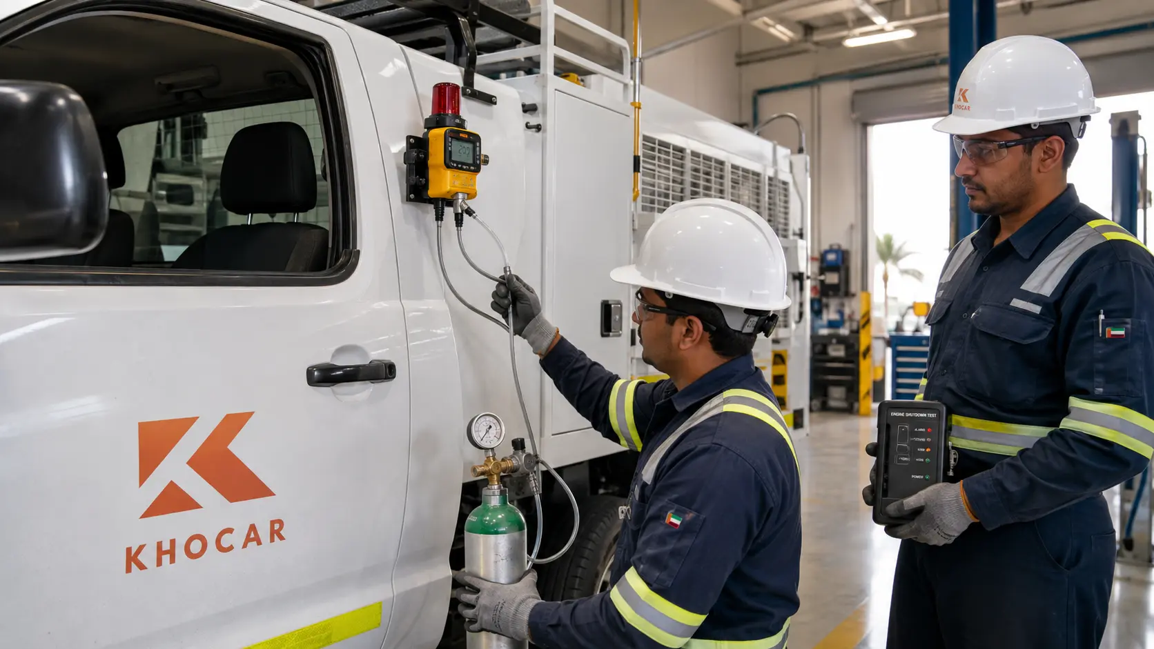
A Zone 2 vehicle can look completely inspection-ready while its gas detector is quietly unable to protect anyone. The display may power up, the indicator lights may flash and the previous calibration sticker may still be visible, yet a blocked inlet, expired sensor, incorrect alarm setting or broken shutdown relay can remain hidden until the system is exposed to gas. That is why understanding gas detector bump test vs calibration is more than a workshop detail for UAE fleet teams; it is a practical safety and mobilization issue.
A bump test asks whether gas can reach the sensor and whether the detector responds and alarms. A calibration check asks whether the displayed response is acceptably close to a known test-gas concentration. A full calibration adjusts the detector when accuracy has drifted. On some Zone 2 vehicles, a separate functional test must also prove that the detector, audible and visual warnings, control relay and automatic engine shutdown work together.
This guide from KhoCAR explains each test, how frequency should be set, what records matter, what to do after a failure and how UAE conditions can affect a Zone 2 vehicle gas detector.
Key Takeaways
A bump test is a functional go/no-go check; calibration is an accuracy process. A proper bump test exposes the sensor to suitable challenge gas and confirms that gas reaches the sensing element and that the expected alarms activate. It does not, by itself, prove that the displayed value is accurate. A calibration check compares the reading with a known, traceable gas concentration, while a full calibration changes the instrument response so it matches that reference within the manufacturer’s procedure.
For fleet teams, the detector is only one part of the safety chain. Portable monitors are commonly function-checked before each day’s use under manufacturer guidance. A vehicle-integrated detector must follow its specific manual, approved design, project procedure and site requirement. Where the detector commands an alarm or engine shutdown, the fleet also needs a documented loop test proving the sensor, controller, indicators, relay and shutdown device respond together. A calibration sticker alone does not prove the complete Zone 2 vehicle system is ready.
Gas Detector Bump Test vs Calibration: The Quick Answer
The fastest correct answer is simple: a bump test checks function, a calibration check checks accuracy and a full calibration adjusts accuracy. Fleet records should name the activity precisely. Writing “tested” or “calibrated” when only the horn was heard creates a misleading record and can hide a failed sensor or shutdown circuit.
The distinction is consistent with the current OSHA guidance for direct-reading monitors, which separates qualitative bump testing from quantitative calibration checks and full adjustment. OSHA also stresses that the manufacturer’s procedure controls the test gas, accessories, acceptable tolerance and calibration method.
| Point | Bump test | Calibration check | Full calibration |
| Primary question | Does the detector respond and alarm? | Is the response acceptably close to the known gas value? | Can the instrument be adjusted to match the known reference? |
| Nature of test | Qualitative function check | Quantitative verification | Quantitative adjustment |
| Changes settings? | No | No | Yes, where the model permits adjustment |
| Typical evidence | Pass/fail, response time and alarm activation | Observed reading versus cylinder concentration and allowed tolerance | Before/after results and calibration certificate or record |
| If it fails | Investigate setup; calibrate before use or remove from service | Perform full calibration | Remove from service for repair or sensor replacement if calibration cannot pass |
| Vehicle-system scope | Can include alarm, relay and shutdown response if the approved procedure calls for a loop test | Usually checks detector accuracy; it may not prove the vehicle shutdown loop | Adjusts the detector; a separate functional loop test may still be required |
Why Gas Detection Matters on a Zone 2 Vehicle
A Zone 2 hazardous area is one where an explosive gas atmosphere is not expected during normal operation and, if it occurs, is expected to exist only briefly. That definition, explained by the UK regulator in its hazardous-area classification guidance, does not mean the area is risk-free. It means ignition controls must be appropriate to a lower-probability but still credible release.
A normal diesel pickup, service truck, generator carrier or mobile workshop can introduce hot surfaces, electrical switching, static discharge and a running engine into that environment. Depending on the project and vehicle use, the approved Zone 2 modification may include exhaust spark control, intake shutdown protection, emergency isolation, anti-static measures, certified electrical components, gas detection and warning or shutdown logic. No single component makes the whole vehicle compliant.
The gas detector’s job is to identify the target hazard early enough for the designed response. That response may be an audible and visual warning, a signal to the driver, an automatic engine shutdown or a combination. The exact target gases, sensor technology, alarm levels, delays, detector position and voting logic must come from the approved design and written project requirement—not from assumptions copied from another vehicle.
| Important distinction: A detector that is certified for use in a hazardous area is not automatically suitable for every Zone 2 vehicle application. Certification, gas range, environmental rating, installation location, wiring, alarm logic and shutdown integration all need to match the documented use case. |
How a Vehicle-Integrated Detector and Shutdown Loop Works
A vehicle-integrated gas detection system is best understood as a chain. Each link must work for the final protective action to occur:
- Gas reaches the detector. The inlet, sinter, filter or sample path must be open and positioned so the intended hazard can be detected.
- The sensor responds. The sensing element must still have adequate sensitivity to the target gas and environmental conditions.
- The controller interprets the signal. The configured gas type, units, range, alarm threshold, delay and fault logic must match the design.
- Warnings activate. Audible and visual indicators must be noticeable from the driver’s operating position and any required external location.
- The relay or digital output changes state. The control output must reach the shutdown circuit without a broken wire, bypass or incorrect logic state.
- The engine or equipment reaches the designed safe state. The shutdown device must operate as intended and must not create another hazard during testing.
This concept resembles the system-level safety philosophy in ADNOC’s public Fire and Gas System Specification, where fire and gas detection can initiate alarms and executive actions such as shutdown. That plant specification should not be treated as a vehicle conversion checklist, but it illustrates why an alarm-only test is not the same as proving the complete protective action.
A Realistic Fleet Example
Imagine a diesel service truck scheduled to enter an Abu Dhabi oilfield. Its detector display starts normally and the calibration label is current. During the pre-mobilization test, challenge gas makes the reading rise and the beacon flash, but the engine keeps running. The detector itself may be healthy; the fault could be a bypassed relay, broken interlock wire, incorrect controller output, failed shutdown solenoid or change made during recent electrical work. A detector-only bump test would miss that system failure unless the approved test procedure also checks the shutdown loop.
What Is a Gas Detector Bump Test?
A bump test, also called a function check, briefly exposes the detector to an appropriate concentration of challenge gas. Its purpose is to show that gas reaches the sensor and that the instrument produces the expected functional response. Manufacturer Dräger describes a bump test as a quick application of known gas that should trigger the alarm while not measuring the accuracy of the displayed reading.
What a Proper Bump Test Can Verify
- The selected challenge gas reaches the sensing element through the normal inlet or approved adapter.
- Each relevant sensor channel responds rather than remaining at zero or fault.
- The low and/or high alarm activates according to the manufacturer or site test method.
- Audible, visual and vibration alarms operate where applicable.
- Fault indicators, remote beacons, relays and shutdown outputs operate if they are included in the approved functional test.
- The detector responds within the maximum time allowed by its procedure, rather than eventually alarming after an unexplained delay.
What a Bump Test Does Not Prove
A basic bump test does not prove that the reading is accurate across the measuring range. It does not automatically verify every alarm setpoint, detector location, Ex installation detail, cable gland, enclosure seal, emergency stop device or vehicle shutdown component. It also does not replace calibration when the model or procedure requires calibration.
This is why the test record should state the scope. “Detector bump passed” and “complete gas-detection shutdown loop passed” are different results. The second requires confirmation that the final control element actually reached its designed safe state.
A Safe, Repeatable Bump-Test Workflow
The exact steps must come from the detector and vehicle-system manuals. A well-controlled fleet procedure normally includes the following sequence:
- Prepare a safe test location. Park the vehicle, control ignition sources and follow the workshop or site permit requirements.
- Verify the asset. Confirm the vehicle number, detector model, serial number, sensor channels and approved test procedure.
- Inspect the detector and system. Look for damage, blocked openings, loose wiring, overdue service, fault codes, bypasses and flat batteries.
- Check the test-gas cylinder. Confirm gas type, concentration, certificate or traceability information, cylinder pressure and expiry date.
- Use the specified accessories. Fit the correct regulator, tubing, flow rate and adapter. Incorrect tubing or a leaking connection can produce a false failure or false pass.
- Apply gas for the specified time. Observe each channel, response time and alarm state without improvising the exposure.
- Verify outputs included in scope. Check the beacon, horn, relay and automatic shutdown if the procedure requires a full loop test.
- Record the result. Capture pass/fail, observed response, gas-cylinder details, operator, time and any corrective action.
- Stop after failure. Do not mobilize the vehicle until the cause is corrected and the required calibration or repair has passed.
What Is Gas Detector Calibration?
Gas detector calibration establishes or restores the relationship between sensor output and a known reference gas. The phrase is often used loosely, so fleet teams should distinguish a calibration check from a full calibration.
Calibration Check
A calibration check exposes the detector to a known, traceable concentration and compares the displayed value with that reference. The reading must fall within the tolerance specified by the manufacturer, site program or applicable procedure. OSHA notes that manufacturer tolerances are commonly expressed as a percentage of the applied gas, but the correct acceptance range must come from the specific detector documentation—not a generic fleet rule.
Full Calibration
A full calibration adjusts the instrument response so it agrees with the certified reference gas. Many instruments perform this adjustment automatically through a menu or docking station; others require qualified service software or workshop intervention. If the sensor cannot be adjusted into tolerance, it should be removed from service for inspection, sensor replacement or manufacturer support.
Zero and Span
A typical full calibration has two reference points. Zero calibration establishes the clean-air baseline. The procedure may require verified clean ambient air or zero-air gas because “outside air” near a workshop, exhaust, solvent store or process area may not be clean. Span calibration applies a certified gas concentration and adjusts the detector response to that value. Using the wrong gas, wrong concentration, expired cylinder, incorrect correction factor or unsuitable flow can create a calibration record that looks complete while making the detector less trustworthy.
Environmental conditions matter as well. OSHA explains that temperature and humidity can change sensor response and advises calibrating as close as practical to the conditions in which the instrument will be used. For a UAE fleet moving between an air-conditioned workshop and extreme outdoor heat, the manufacturer’s stabilization and environmental instructions deserve particular attention.
How Often Should a Zone 2 Vehicle Gas Detector Be Tested?
There is no responsible universal interval that applies to every gas detector on every UAE Zone 2 vehicle. Frequency depends on whether the device is portable or permanently installed, the detector model, sensor technology, approved vehicle design, project requirement, site procedure, exposure history, operating environment and previous test results.
For portable direct-reading monitors, the ISEA validation statement recommends a bump test or calibration check before each day’s use in accordance with the manufacturer’s instructions. It also says a failed instrument must be fully calibrated before further use or removed from service. Full calibration is performed at regular intervals defined by the manufacturer, company policy or relevant authority.
A fixed or vehicle-integrated detector may have a different maintenance strategy. Fleet teams should not copy a portable-monitor schedule without checking the installed-system manual and project documentation. The integrated system may require separate sensor calibration, functional gas challenge, alarm test and end-to-end shutdown test at different intervals.
| Asset or test | Functional verification | Calibration or deeper test | What must be proven |
| Portable personal monitor | Before each day or shift of use under manufacturer guidance | At the manufacturer/site interval and immediately after specified triggers | Gas response, alarms and reading accuracy |
| Vehicle-integrated detector | At the interval in the approved vehicle and detector procedure; often also before mobilization | Per detector manufacturer, project plan and test history | Sensor, local alarm and controller response |
| Complete shutdown loop | During pre-mobilization or scheduled proof testing as specified | After repair, wiring changes, detector replacement or failed test | Detector, relay, warning devices and final shutdown action |
| Stored spare detector | Before issue to a vehicle or operator | Per storage and manufacturer requirements | Battery, sensor health, expiry status and gas response |
Events That Should Trigger Immediate Revalidation
- A failed bump test, calibration check, self-test or fault alarm.
- Exposure to an over-range concentration or a known sensor poison or inhibitor.
- A hard impact, liquid ingress, severe vibration, blocked inlet or suspected physical damage.
- Detector, sensor, controller, relay, shutdown valve, wiring or software replacement.
- Vehicle electrical work, battery isolation changes or modifications near the shutdown circuit.
- A change in custody, long storage period, new work environment or uncertainty about the instrument history.
- Any reading that conflicts with another trusted detector or with known site conditions.
Honeywell’s technical note on calibration intervals describes a risk- and history-based approach: start with frequent verification in the intended atmosphere, retain the instrument history and never extend the interval beyond the user guide. That is a useful management principle, but the current manual for the installed model still controls.
How UAE Conditions Can Affect Sensor Reliability
UAE fleet equipment operates in conditions that can expose weaknesses faster than a clean laboratory environment. The risk is not simply “heat damages detectors.” Different sensor technologies react differently, and some instruments are designed for harsh conditions. The practical point is that heat, humidity, dust, vibration and contaminants must be considered when setting verification frequency and investigating drift.
| Condition | Possible effect | Fleet response |
| High temperature or rapid temperature change | Slow response, drift, shortened battery life or readings outside environmental specification | Allow stabilization; verify operating range; repeat the required check under representative conditions |
| Dust and airborne particulates | Blocked inlet, delayed response or reduced gas flow | Inspect and replace filters as specified; do not clean sensing surfaces with unapproved solvents |
| Humidity, condensation or liquid ingress | Unstable readings, sensor fault or damaged electronics | Dry and service according to the manual; revalidate before use |
| Vibration and impact | Loose connection, cracked enclosure, relay fault or internal damage not visible from outside | Inspect wiring and enclosure; perform detector and full-loop test |
| Silicones, solvents and corrosive vapours | Poisoned or inhibited LEL/electrochemical sensor with weak or no response | Remove exposure source; calibrate; replace sensor if it cannot pass |
| High target-gas exposure | Over-range indication, saturation or temporary/permanent loss of sensitivity | Follow recovery procedure and verify accuracy before reuse |
The OSHA calibration bulletin specifically identifies temperature, humidity, airborne particles, high gas concentrations, solvent vapours, sensor poisons, shock and vibration as causes that can affect sensor performance. A fleet operating in Musaffah, remote desert sites or process areas should therefore use actual test history—not calendar dates alone—to identify detectors that drift repeatedly.
What to Do When a Gas Detector Fails a Bump Test
A failed bump test is a stop signal, not an inconvenience to clear by repeating the test until the screen turns green. The vehicle or detector should be held from the relevant hazardous-area task until the cause is understood and the required corrective test passes.
Step 1: Confirm the Test Setup
- Is the cylinder the correct gas and concentration for every sensor being tested?
- Is the cylinder within its expiry date and does it have enough pressure?
- Is the correct demand-flow or fixed-flow regulator fitted?
- Are the tubing material, length, adapter and flow direction correct?
- Is gas leaking at a connection or bypassing the sensor inlet?
- Did the detector complete its warm-up and self-test without faults?
Manufacturer support material on common bump-test failures highlights issues such as expired or insufficient gas, incorrect tubing, docking-station communication and instruments that do not alarm properly. These checks help separate a test-rig problem from a detector fault, but they do not authorize returning a failed detector to service.
Step 2: Inspect the Detector and Gas Path
Check the inlet, hydrophobic filter, sinter, pump, sample line, enclosure, power supply and wiring. A monitor may display normal startup information even when gas cannot physically reach the sensor. For an integrated vehicle system, confirm that no temporary cap, paint, dust cover or recent body repair is blocking the detector.
Step 3: Perform the Required Calibration or Service
If the setup is correct and the bump test still fails, perform the manufacturer-approved full calibration. If calibration fails, remove the detector from service and arrange qualified repair or sensor replacement. After repair, repeat the accuracy check and the complete functional loop test before releasing the vehicle.
| Never normalize a failure: Do not increase test-gas exposure indefinitely, alter alarm thresholds to force a pass, bypass the shutdown, use an open flame or unapproved gas source, or overwrite the record. Correct the cause and produce a traceable pass result. |
Choosing and Managing Calibration Gas
The detector is only as trustworthy as the reference used to test it. A cylinder labelled “test gas” is not enough. The gas species, balance gas, concentration, uncertainty or certificate information, expiry, regulator and delivery materials must be compatible with the detector and procedure.
Calibration-Gas Checklist
- Correct gas species: Match every installed sensor channel, including combustible-gas response and any cross-sensitivity instructions.
- Correct concentration: Use the concentration and tolerance required by the detector manual or approved procedure.
- Traceability: Keep the cylinder certificate or analysis information required by the project or calibration system.
- Valid shelf life: Reactive gases such as H2S can have limited stability; never use a cylinder after its stated expiry.
- Correct regulator and flow: Too little flow may not reach the sensor; excessive or forced flow may distort the test or damage components.
- Compatible tubing: Some reactive gases can be absorbed by unsuitable tubing, delaying or reducing the concentration that reaches the sensor.
- Controlled storage: Protect cylinders from excessive heat, corrosion, damage and unauthorized use; rotate stock by expiry.
OSHA advises using certified, traceable gas before its expiry and retaining the certificate of analysis. For a fleet, the simplest control is a calibration-gas register showing cylinder ID, mixture, concentration, received date, expiry, assigned station and remaining pressure. That prevents a single expired cylinder from generating repeated false failures across several vehicles.
Records, Certificates and Site-Access Evidence
A reliable maintenance program should make it possible to reconstruct what happened without relying on memory. For every test, record the vehicle, detector and gas cylinder as separate assets. At minimum, capture:
- vehicle fleet number, registration or project asset ID;
- detector make, model, serial number and installed sensor channels;
- test type: self-test, bump test, calibration check, full calibration or complete shutdown-loop test;
- date, time, location, responsible person and applicable procedure revision;
- test-gas manufacturer, cylinder ID, gas mixture, concentration and expiry;
- observed reading, alarm response, response time and pass/fail criteria where required;
- relay, beacon, horn and engine-shutdown result for integrated-system tests;
- fault found, repair completed, parts replaced and final retest result;
- next due date and any restrictions on use.
The international Ex framework is built around standards for selection, installation, inspection and maintenance; the IECEx standards overview identifies the IEC 60079 series as a foundation for equipment used where fire or explosion potential exists. The precise standards and certificates relevant to a vehicle must be confirmed by the project’s competent technical authority.
For laboratory calibration, the Emirates International Accreditation Centre’s calibration-laboratory program uses ISO/IEC 17025:2017. ISO explains that ISO/IEC 17025 addresses laboratory competence and reliable results. Accreditation alone is not enough: verify that the laboratory’s current scope includes the detector type, gas measurement and method you need.
Why a Calibration Certificate Is Not the Whole Vehicle File
A certificate can show that a detector was calibrated at a certain time under a defined method. It does not automatically prove that the detector was installed in the correct position, that the Ex enclosure remains intact, that alarm settings match the project, or that the vehicle shutdown circuit works. Fleet teams preparing for mobilization should review detector records alongside installation documents, component certificates, wiring information, shutdown tests and the current site checklist. KhoCAR’s guide to common Zone 2 vehicle inspection failures explains how missing records and incomplete system functionality can delay site access.
A Practical Gas-Detection Workflow for UAE Fleet Teams
The best fleet program makes the safe action the easy action. Drivers should not have to guess which test is due, and workshop teams should not discover an expired gas cylinder on the morning of mobilization.
Suggested Ten-Step Control Process
- Create one asset register. Link every detector serial number to its vehicle and project use.
- Collect controlled manuals and requirements. Keep the current detector manual, approved vehicle design, project checklist and test procedure together.
- Define test categories clearly. Use separate codes for self-test, bump test, calibration check, full calibration and shutdown-loop test.
- Assign responsibility. Specify what the driver checks, what HSE witnesses, what the workshop performs and what requires an accredited lab or qualified integrator.
- Set frequencies from evidence. Use manufacturer limits, project rules, site expectations, environmental exposure and historical drift.
- Control calibration gas. Maintain stock, expiry alerts, certificates, regulators, tubing and adapters.
- Build pre-mobilization verification into dispatch. Do not treat gas detection as paperwork after the vehicle is already scheduled.
- Quarantine failures visibly. Use an electronic lockout or physical tag so another shift cannot issue the vehicle accidentally.
- Retest the complete system after intervention. Detector repair alone does not prove alarm and shutdown operation.
- Review trends monthly. Repeated failures by sensor type, vehicle, workshop station or cylinder batch can reveal a systemic problem.
| Role | Core responsibility | Should not assume |
| Driver/operator | Visual check, status/fault review, required pre-use verification and immediate reporting | Issue or operate a failed or overdue detector |
| Fleet manager | Asset register, due-date control, spare coverage and dispatch hold points | Change technical acceptance limits without authority |
| HSE/project team | Confirm current site requirement, witness scope and retain evidence | Assume a calibration sticker proves complete Zone 2 readiness |
| Workshop/Zone 2 integrator | Inspect installation, wiring, alarms, relay and shutdown action; document repair | Calibrate outside manufacturer procedure or bypass protection to obtain a pass |
| Calibration laboratory | Perform activities within its approved method and accreditation scope; issue traceable results | Certify vehicle-system integration unless that activity is actually within scope |
Common Gas Detector Bump Test and Calibration Mistakes
Treating the power-on self-test as a bump test. A self-test can check electronics, battery and alarm devices without proving that target gas reaches and activates the sensor.
Assuming a bump pass proves accuracy. The alarm may activate even when the displayed concentration is materially inaccurate. Use the required calibration check to verify accuracy.
Using expired or mismatched gas. A weak reactive-gas cylinder or wrong mixture can create false failures, false confidence or an invalid calibration.
Zeroing in contaminated air. Workshop exhaust, solvents or process gas can shift the baseline. Use the manual’s clean-air or zero-air method.
Testing the detector but not the shutdown loop. A healthy sensor cannot stop an engine through a broken, bypassed or incorrectly configured output circuit.
Applying one schedule to every detector. Sensor technology, manufacturer limits, use pattern and exposure history can differ across the fleet.
Ignoring changes after calibration. Wiring work, software settings, relocation, body repair and battery isolation can affect the installed system after the detector was calibrated.
Keeping only the certificate. Fleet readiness also depends on installation, functional testing, repair history and site-specific documentation.
Three Realistic Fleet Scenarios
Scenario 1: The Detector Powers On but Gas Cannot Reach It
A pickup has been washed and detailed before inspection. The detector starts normally, but the bump test fails. The workshop finds that a protective cover used during cleaning was never removed from the inlet. The lesson is simple: an electronic self-test cannot prove the gas path is open. After the obstruction is removed, the detector receives the required calibration check and functional retest before release.
Scenario 2: The Detector Alarms but the Engine Does Not Stop
A mobile workshop returns from electrical repair. Challenge gas causes the detector and beacon to alarm, but the diesel engine continues running. Investigation finds a disconnected relay wire near the battery isolator. The detector passes its individual response check, yet the vehicle fails the integrated shutdown test. The repair is documented and the complete loop is retested.
Scenario 3: Several Vehicles Fail at the Same Docking Station
Three detectors fail within one hour. Rather than replacing three sensors, the supervisor checks the common test setup and finds an expired H2S cylinder with low pressure. A replacement certified cylinder produces valid results. The fleet still retains all failed records and corrective actions, because deleting them would hide an important weakness in calibration-gas control.
How to Select Qualified Gas Detector and Zone 2 Support
Fleet teams may need two complementary capabilities: competent detector calibration and competent vehicle-system integration. One provider may offer both, or separate specialists may be involved. Before awarding work, ask:
- Which detector brands, models, sensor types and gas ranges can you test and service?
- Are your procedures based on the current manufacturer manuals and approved vehicle documentation?
- Can you provide traceable gas details, before/after results and clear pass/fail criteria?
- If laboratory accreditation is required, is this exact activity included in the current scope?
- Can you test the installed alarm, relay and automatic shutdown as a complete loop?
- Can you diagnose wiring, controller, shutdown-device and installation faults—not only calibrate the sensor?
- Will the final file identify every vehicle and detector by serial or fleet number?
- How are failed instruments quarantined, repaired and retested?
A technically strong provider will also be comfortable saying when the project’s written requirement must be clarified. “Zone 2” is not a universal parts list, and a responsible workshop should confirm the intended vehicle, hazardous-area access, detector function and documentation before promising a configuration.
Final Takeaway
The practical answer to gas detector bump test vs calibration is that both are necessary, but they answer different questions. A bump test proves basic gas response and alarm function. A calibration check verifies accuracy against known gas. A full calibration corrects the detector when its response is outside tolerance. For a Zone 2 vehicle gas detector, fleet teams must go one step further and prove that the alarm, relay and automatic engine shutdown operate as one protective system wherever that function is part of the approved design.
The safest schedule is not copied from another fleet. It is built from the detector manual, current project and site instructions, environmental exposure, asset history and documented test results. Before mobilization, confirm the exact vehicle configuration and evidence your project expects. If the detector, wiring or shutdown response is uncertain, contact KhoCAR early enough to assess the system before the site-access deadline.
Need Help With a Zone 2 Vehicle Gas Detection and Shutdown System?
KhoCAR supports UAE contractors preparing vehicles and mobile equipment for hazardous-area work. If your fleet needs a gas detector integrated with warning or shutdown controls, an existing system inspected after repair, or the wider conversion reviewed before mobilization, explore KhoCAR’s Zone 2 installation and certification services in Abu Dhabi. Share the vehicle type, project requirement, detector model, current faults and mobilization deadline so the assessment can start with the right technical information.
FAQs
What is the main difference between a gas detector bump test and calibration?
A bump test is a functional check that confirms gas reaches the sensor and the expected alarms activate. A calibration check compares the displayed reading with a known test-gas concentration to verify accuracy. A full calibration adjusts the detector response when it is outside the permitted tolerance. The three terms should not be used interchangeably in fleet records.
How often should a gas detector be bump tested?
For portable direct-reading monitors, ISEA and OSHA guidance supports verifying operation before each day’s use in accordance with the manufacturer’s instructions. A fixed or vehicle-integrated detector may follow a different interval defined by its manual, approved system design, site procedure and exposure history. Additional tests may be required before mobilization or after repair, impact, over-range exposure or suspected contamination.
How often is gas detector calibration required in the UAE?
There is no single UAE interval that safely applies to every model and project. Full calibration should follow the detector manufacturer, internal HSE program, project specification and site requirement. The interval may need to be shortened when sensors experience heat, humidity, dust, vibration, poisons, high gas exposure or repeated drift. Never extend the manufacturer’s maximum interval without authorized technical justification.
Is a bump test the same as a gas detector self-test?
No. A self-test may check the battery, electronics, display, horn, lights and internal diagnostics, but it may not expose the sensor to target gas. A bump test uses suitable challenge gas to prove that gas can reach the sensor and trigger the required response. Both may be useful, but a successful power-on sequence does not replace a required gas challenge.
Can a gas detector pass a bump test and still be inaccurate?
Yes. A detector can respond strongly enough to activate an alarm while its numerical reading is outside the acceptable accuracy tolerance. That is why a qualitative bump test and a quantitative calibration check answer different questions. Where accurate concentration values or setpoint verification matter, use the calibration-check procedure specified by the manufacturer or site program.
What should I do if a Zone 2 vehicle gas detector fails a bump test?
Hold the vehicle or detector from the relevant hazardous-area task. Confirm the test setup, gas type, cylinder expiry, pressure, regulator, tubing, adapter and detector inlet. If the setup is correct, perform the approved full calibration. A detector that cannot pass calibration should be removed for repair or sensor replacement. Retest the complete alarm and shutdown loop before release.
What gas should be used for a bump test or calibration?
Use the gas species, concentration, balance gas, regulator, flow and adapter specified for the detector and test procedure. The cylinder should be certified or traceable as required and must be within its expiry date. Multi-gas detectors may require an approved mixture. Reactive gases such as H2S can be affected by cylinder age and unsuitable tubing, so accessory compatibility matters.
Does a calibration certificate prove a Zone 2 vehicle is ready for site access?
Not by itself. A certificate can document detector calibration, but it may not prove correct installation, hazardous-area suitability, alarm configuration, enclosure integrity, relay operation or automatic engine shutdown. Site readiness normally requires a broader file covering the approved vehicle configuration, component certificates, installation evidence, functional testing, repair history and current project checklist.
Should the engine shutdown be tested every time the detector is bump tested?
That depends on the approved design and written procedure. Some routine tests may verify only detector response and alarms, while scheduled proof tests or pre-mobilization checks may require the complete shutdown loop. The fleet should clearly document which scope was tested. If the relay, wiring, controller or shutdown device has been repaired or changed, an end-to-end test is essential before release.