
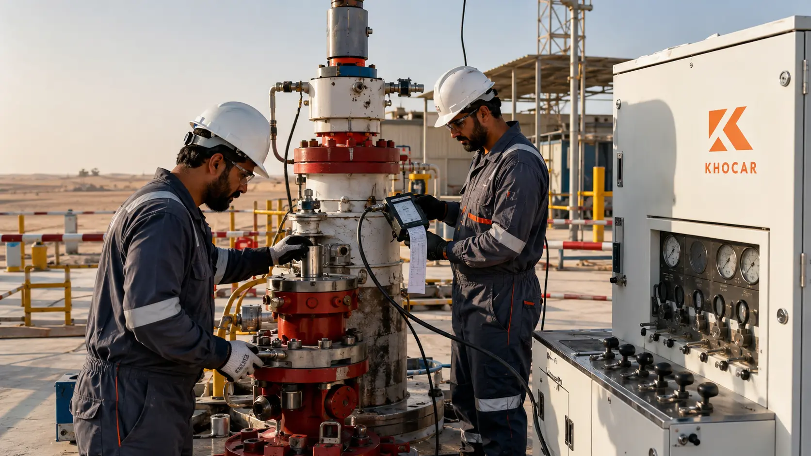
Wireline pressure control equipment can look complete on the rack and still be unready for the well. A lubricator may have the required length but the wrong quick union. A wireline valve may carry the right nominal pressure rating but lack evidence for the intended sour service. A fresh pressure-test certificate may exist, yet the job program, wellhead connection, line size or maximum anticipated surface pressure has changed. In UAE oilfields, those gaps can turn a short intervention into a delayed mobilization, a failed pre-job test or a barrier-management problem with consequences far beyond the schedule.
This guide gives wireline supervisors, HSE teams, maintenance crews and procurement staff a practical way to review the PCE string before it reaches the wellsite. It explains the major components, what working-pressure and compatibility data mean, how pressure-test planning should be controlled, what documentation belongs in the equipment dossier, and which warning signs demand quarantine or technical review. The aim is not to replace the approved procedure. It is to help teams ask the right questions early, close evidence gaps, and coordinate with a capable UAE partner such as KhoCAR Services before the mobilization window becomes critical.
Key Takeaways
Wireline PCE is a pressure-containing system, not a collection of interchangeable parts. Every component must be suitable for the same job envelope: well pressure, bore, wire or cable, connection profile, temperature, well fluids, H2S classification, lifting arrangement and operator program. The lowest-rated or least-compatible element governs the usable string. A certificate is valuable only when it can be matched to the exact serial-numbered equipment, current configuration and defined test. Pressure testing must therefore be planned from approved well data and procedures, performed by competent personnel from a protected position, and recorded with calibrated instruments and clear acceptance criteria. For UAE mobilizations, build the PCE dossier before dispatch, verify interfaces and consumables in the workshop, and treat any unexplained leak, damaged pressure boundary, mixed connection, expired record or sour-service uncertainty as a stop-and-review condition.
What Is Wireline Pressure Control Equipment?
Wireline pressure control equipment (PCE) is the surface equipment assembled above a pressurized well to allow wireline or slickline tools to enter, operate in and return from the well while maintaining pressure containment and a controlled barrier system. Its exact configuration changes with the conveyance method, well conditions, tool string and operator requirements.
A typical string connects to the wellhead or tree through an adaptor. Above that interface, one or more wireline valves provide a closure function around or across the line; lubricator sections create enough pressure-containing length to house the tool string; a stuffing box or grease injection control head seals around the moving line at the top; and supporting components provide pumping, tool trapping, control, lifting and test functions. The system must be reviewed as one pressure-control envelope because a compatible 10,000 psi component cannot make a 5,000 psi component suitable for a 10,000 psi job.
The BSEE wireline equipment description defines the wireline unit, for pressure-control purposes, from the wireline BOPs connected to the tree or drilling BOPs through to the pressure-control head at the top. That boundary is useful for thinking about interfaces, but it is not a UAE operating rule. The operator-approved well program and project standards define the actual barrier philosophy, equipment scope and test requirements for each job.
Wireline PCE vs Slickline PCE: Is There a Difference?
“Wireline PCE” is often used as the broad category. “Slickline PCE” usually refers to equipment configured for a single-strand solid wire, while electric-line or braided-line systems use different dynamic sealing arrangements and may require grease injection. The terms can overlap in supplier catalogues, so the name alone is not enough for selection.
| Term | Typical conveyance | Top seal concept | Selection questions |
| Slickline | Single solid wire, commonly small diameter | Stuffing box and packing selected for the actual wire | Wire diameter, packing condition, sheave groove and line cleanliness |
| Braided line | Multi-strand mechanical line | Grease injection or a purpose-designed control head | Grease type, injection pressure/capacity, flow tubes and cable OD |
| Electric line | Armoured cable carrying electrical signals/power | Grease injection control head configured for the cable | Cable OD, head components, grease system and electrical-line handling |
| Generic “wireline” request | May mean any of the above | Cannot be assumed | Clarify conveyance, line size, well data and operator configuration before quoting |
When requesting equipment, state the line type and exact outside diameter rather than asking only for “wireline PCE.” This single clarification prevents many packing, flow-tube, sheave and wireline-valve mismatches.
Why PCE Readiness Matters in UAE Oilfield Operations
Well intervention often works inside a narrow operational window. The production team may have prepared the well, the crane and crew may be booked, and access permits may be time-limited. Yet the PCE cannot be selected from schedule pressure. A missed interface or uncertain rating can affect well control, personnel exposure, equipment integrity and the ability to complete the task.
UAE conditions add practical stressors: high ambient temperature, airborne sand and dust, long road mobilizations, remote locations and repeated handling. These do not automatically change a manufacturer rating, but they can degrade elastomers, contaminate sealing surfaces, loosen fittings, obscure markings and make hydraulic or grease systems less reliable. Storage and transport controls therefore belong inside the readiness plan, not after the field test fails.
Pressure-control expectations are also receiving fresh attention internationally. A BSEE safety assessment published in January 2026 applies structured success-path and failure-mode analysis to wireline operations. It is not UAE regulation, but it reinforces a useful principle: safe wireline work depends on understanding how equipment, people, procedures and supporting systems combine to preserve the intended safety function.
Main Components of a Wireline Pressure Control Equipment String
The final stack is job-specific. The following component map helps non-specialists understand what each part contributes and what evidence should be checked. It is not a rig-up order.
| Component | Primary function | Key verification points |
| Wellhead adaptor / flange | Connects the PCE string to the tree or wellhead | Correct profile, pressure class, bore, material, seal and verified wellhead interface |
| Wireline valve / wireline BOP | Provides a pressure-control closure function around the line or, with appropriate rams, across the bore | Ram type and size, operating system, closing function, seals, body/bonnet condition and certification |
| Lubricator sections | Provide pressure-containing length to house the complete tool string above the closed well | Usable internal length, ID, connection compatibility, straightness, wall/pressure-boundary condition and lifting points |
| Tool trap / catcher | Helps detect or retain the tool string at a planned position | Correct insert/flapper, function, bore clearance, orientation and control indication |
| Pump-in / bleed-off sub | Provides controlled access for pressure equalization, pumping, bleeding or test connection as designed | Valve/port rating, caps, hose compatibility, flow path and procedure-defined use |
| Quick-test sub | Allows sections of the assembled string to be retested with less disturbance when permitted | Seal condition, correct profile, pressure rating and approved test method |
| Stuffing box | Creates a dynamic seal around moving slickline | Packing matched to wire size, gland condition, sheave alignment, drain/control arrangement and spares |
| Grease injection control head | Uses controlled grease flow and close-clearance tubes to seal around braided/electric line | Cable OD, flow-tube sizes, grease specification, pumps, return/pressure capability and hoses |
| Control panel / hydraulic unit | Operates hydraulic valves, tool traps or auxiliary functions | Pressure settings, gauges, accumulators, hose condition, labeling, emergency controls and functional test |
| Sheaves and lifting accessories | Guide the line and support controlled rig-up/operation loads | SWL/WLL, inspection status, groove compatibility, guards, bearings, anchors and lift plan |
Manufacturer product ranges show why a generic request is risky. NOV’s slickline PCE string overview describes configurations from a basic 2½-inch-ID, 5,000 psi working-pressure string to systems rated at 15,000 psi with bores up to 9 inches. Those are product-range examples—not default requirements. The correct size and rating must be selected from the actual well and job envelope.
The Five Compatibility Checks That Govern the Whole String
1. Pressure Rating
Record the working-pressure rating for every pressure-containing component, adaptor, union, valve, sub, head and hose exposed to well pressure. Do not average ratings. The lowest acceptable rating or any unverified component constrains the string. Confirm whether markings refer to working pressure, test pressure, cold working pressure or another defined value; these terms are not interchangeable.
2. Bore and Tool Clearance
The minimum internal diameter must pass the planned tool string, connections and fishing neck without creating an obstruction. Lubricator length must contain the full tool assembly with the clearances required by the procedure. Check the assembled tool drawing and measured dimensions—not only a nominal tool family name.
3. End Connections and Seals
Two unions can look similar while using different profiles, pressure classes, seal locations or make-up requirements. Mixed or unidentified unions are a stop condition. Protect seal faces during transport, confirm the correct seal material and condition, and use only the current manufacturer instructions for assembly, torque and inspection.
4. Temperature and Fluid Compatibility
The job envelope includes minimum and maximum temperature, produced fluids, treatment chemicals, completion brines, grease and cleaning products. Metal selection and elastomer selection are separate questions. A body suitable for sour service can still be fitted with an elastomer that swells, hardens or loses sealing performance in the actual temperature/fluid combination.
5. Line and Dynamic-Seal Compatibility
Match slickline packing, grease flow tubes, control-head parts and sheave grooves to the measured line or cable. A small diameter mismatch can cause leakage, excessive friction, wire damage or unstable grease demand. Include line condition and cleanliness in the review because damaged or contaminated line can defeat an otherwise correct seal package.
Which Standards Apply to Wireline PCE?
There is no safe one-line answer. Applicability depends on the component, design basis, manufacturer, operator specification, well service and contract. The procurement file should identify the required standard and edition rather than relying on a generic “API certified” statement.
The current API Specification 6A announcement describes the 21st edition as requirements for wellhead and tree equipment. API’s Spec 6A scope summary covers design, materials, testing, inspection, marking, handling, shipment, purchasing, repair and remanufacture for that equipment family. Whether and how a particular PCE component is within a specified standard must be confirmed from its certified design documentation and the operator’s requirements.
For H2S-containing production environments, ISO 15156-1:2020 sets general principles for selecting cracking-resistant materials. The equivalent AMPP listing identifies ANSI/NACE MR0175-2021/ISO 15156-2020. A statement such as “NACE compliant” should therefore lead to more questions: which materials, environmental limits, hardness controls, manufacturing records and exact equipment configuration support the claim?
IOGP also maintains a reference list for well-integrity and well-control standards. Use such international material as a technical reference, then apply the operator’s current UAE project documents. Requirements from another jurisdiction can inform good questions, but they do not replace local law, client standards or the approved well program.
Build the Pre-Job Information Package Before Selecting Equipment
A strong pre-job review begins with data, not available stock. The equipment owner, service company and operator should resolve ambiguities before dispatch. At minimum, collect and approve the following information.
| Information group | What to confirm |
| Well and pressure data | Current and anticipated surface pressure, pressure source, temperature envelope, fluid/gas composition and H2S/CO2 status |
| Wellhead/tree interface | Manufacturer, model, outlet size/class, connection profile, bore and current configuration |
| Intervention scope | Slickline, braided line or electric line; job objective; expected operating state; contingency requirements |
| Line/cable | Type, measured OD, construction, condition and required dynamic-seal system |
| Tool string | Full assembly drawing, maximum OD, total length, fishing neck and any centralizers or oversized features |
| PCE design | Stack drawing, component list, serial numbers, pressure ratings, bore and barrier functions |
| Test plan | Medium, test boundaries, target/hold points, acceptance criteria, calibrated instruments, chart/data capture and exclusion zone |
| Lifting and layout | Rig-up height, mast/crane capacity, lifting plan, certified accessories, anchors, working platform and line path |
| Emergency arrangements | Shut-in philosophy, communication, ESD interfaces, contingency tools, roles and stop-work triggers |
| Documentation | Certificates, material/service records, redress history, inspection/test status, manuals and approved procedures |
| Fast rule: If the team cannot state the wellhead connection, maximum anticipated surface pressure, line OD, tool-string length/OD and sour-service status, the PCE selection is not ready to be finalized. |
Pre-Rig-Up Inspection Checklist
The workshop inspection should prove identity, condition and compatibility. It should not be reduced to finding a test sticker. Use the operator-approved checklist and current manufacturer limits, then record the result against serial numbers.
- Identity and traceability: nameplate readable; serial number matches the equipment list, certificates and maintenance system.
- Pressure boundary: no unauthorized weld repair, impact damage, deep corrosion, thread damage, erosion, washout indication or unexplained grinding.
- Connections: profiles match the approved stack drawing; seal faces and threads are clean, protected and free from unacceptable damage.
- Seals and elastomers: correct part/material/batch where required; within shelf-life controls; stored correctly; no flattening, cuts, extrusion or chemical attack.
- Valve and ram function: correct ram or sealing element installed; full travel and position indication verified using the approved functional procedure.
- Lubricators: enough usable length; bore clear; sections straight; lifting clamps and attachments correct for the specific equipment.
- Control system: gauges readable and in calibration; hoses rated, identified and undamaged; fittings secure; accumulators and controls pass the approved functional check.
- Dynamic seal system: packing or flow tubes match measured line OD; grease and consumables meet the approved specification; spares are available.
- Lifting equipment: current inspection, legible WLL/SWL, correct attachment points and no improvised lifting arrangement.
- Documentation: current approved drawings, manuals, certificates, test records, redress history and deviation approvals travel with the equipment dossier.
KhoCAR’s slickline and pressure-control equipment catalogue can help procurement teams identify relevant equipment families and manufacturer information. A catalogue is a starting point: the purchase or rental request still needs the full job envelope and operator acceptance criteria.
How Should Wireline Pressure Control Equipment Be Pressure Tested?
Wireline PCE should be pressure tested only under an approved, job-specific procedure that defines the test boundary, medium, staged pressures, hold periods, acceptance criteria, calibrated instruments, personnel positions and response to leakage or abnormal behavior. This article intentionally does not prescribe universal pressures or valve sequences.
The reason is simple: test requirements depend on the well, component ratings, operator rules and whether the equipment has just been assembled, redressed, transported, partially disturbed or installed on the well. The test must never exceed the rating or limitation of the weakest component, temporary test item or connection. The competent supervisor must also consider stored energy, trapped pressure and line-of-fire hazards.
BSEE’s wireline operations research record describes an industry study focused on how lubricator and wireline BOP tests are conducted, how success is defined, whether tests are charted and why departures were requested from an expected shut-in surface-pressure test. The U.S. rule discussed there is not a UAE requirement. Its broader lesson is relevant everywhere: “pressure tested” is incomplete unless the record identifies what was tested, to what approved criterion, with what evidence and under whose authority.
A Controlled Test Has Six Evidence Layers
| Evidence layer | What good control looks like |
| 1. Approved basis | Current well data, equipment ratings, operator procedure and signed test plan agree. |
| 2. Defined boundary | The drawing identifies every component, valve, blind, adaptor, hose and temporary item exposed to test pressure. |
| 3. Safe setup | Restraints, barriers, exclusion zone, remote observation, communications and bleed-down path are established. |
| 4. Suitable instruments | Pressure recorders/gauges have the required range, accuracy, calibration status and unique identification. |
| 5. Recorded execution | Stages, stabilization, hold time, pressure/temperature behavior, leaks, anomalies and corrective actions are captured. |
| 6. Formal acceptance | Authorized personnel compare the evidence with defined criteria, sign the record and control any retest or deviation. |
Low-Pressure and High-Pressure Checks Serve Different Purposes
Many approved programs use staged testing because some sealing problems are easier to identify at lower pressure and because a controlled progression can verify setup before higher stored energy is introduced. However, the values, sequence and acceptance criteria must come from the approved procedure. A high-pressure hold does not erase an unexplained low-pressure leak, and tightening or striking equipment while pressurized is never an acceptable shortcut.
Pressure Charts Need Context
A smooth line on a chart is not self-explanatory. Temperature change, trapped gas, pump isolation, recorder range and system volume can affect the trace. The record should identify the equipment string, serial numbers, test medium, gauge/recorder IDs, start and finish times, target stages, actual readings, temperature where required, observed leaks, bleed-down confirmation, witnesses and final disposition. Preserve the original data as well as the signed summary.
Sour-Service and H2S Readiness
Sour service is not solved by adding an H2S note to the delivery ticket. H2S can create sulfide-stress-cracking risks in susceptible metallic materials, while the complete environment—including H2S partial pressure, pH, chlorides, temperature and material condition—affects selection. ISO 15156 provides the framework, but application requires competent materials engineering and documented service conditions.
For PCE, confirm body and pressure-containing material qualification, fasteners, rams, springs and other stressed components as applicable. Review welding and repair history, hardness controls, heat treatment, material certificates and manufacturer environmental limits. Separately confirm elastomers, grease, hoses and ancillary items against the chemical and temperature envelope.
- Is the well formally classified for H2S/sour service, and what environmental data supports selection?
- Does each serial-numbered pressure-containing component have evidence for the intended service—not merely a catalogue option?
- Are replacement parts, fasteners, rams and seal kits controlled to the same approved configuration?
- Have coating damage, corrosion, unauthorized repair and hardness-sensitive work been evaluated by a competent person?
- Are H2S detection, breathing-air/escape provisions, muster arrangements and emergency roles defined by the site plan?
- Does the maintenance and test area control exposure to displaced fluids or gas during bleed-down and disassembly?
What Should Be in the PCE Certification and Mobilization Dossier?
The dossier should let an independent reviewer move from the job requirement to the installed equipment and then to the evidence. “Certificate available” is too vague. A useful pack is indexed, revision-controlled and matched to serial numbers.
| Dossier section | Typical evidence |
| Job basis | Approved program, well data sheet, barrier schematic, risk assessment, PCE stack drawing and test procedure |
| Equipment identity | Master component list, manufacturer/model, serial number, pressure rating, bore, connection and service classification |
| Design/manufacture | Applicable standards, conformity records, material certificates, drawings and manufacturer data required by contract |
| Maintenance | Inspection, redress, repair, part replacement and dimensional/NDT records as required |
| Calibration | Current certificates for test gauges, recorders, torque tools and other measurement equipment specified by the procedure |
| Testing | Workshop and field pressure-test records, raw chart/data, test boundary, medium, witnesses, results and corrective actions |
| Lifting | Certificates/register entries for lifting clamps, slings, shackles, sheaves and other job-specific accessories |
| Operations | Controlled manuals, checklists, competence/authorization evidence, emergency plan and approved deviations |
Check dates, but also check scope. A valid calibration certificate for a gauge does not prove the PCE passed. A hydrostatic body test does not automatically prove every assembled connection or control function. A material certificate does not prove the component is still in its original, undamaged configuration. Evidence layers complement one another; they do not substitute for one another.
Common Reasons a Wireline PCE Test or Mobilization Fails
| Observed problem | Why it matters | Corrective direction |
| Wrong or mixed quick union | Sections cannot be safely made up, or a seal/interface is not as designed | Quarantine; identify profiles from controlled manufacturer data; replace with approved matching equipment |
| Damaged seal face or thread | Leakage, incomplete make-up or uncertain pressure integrity | Stop; clean and inspect; obtain competent disposition; do not grind or dress beyond approved limits |
| Incorrect packing or flow tube | Leakage around line, excess friction or unstable grease demand | Verify measured line OD, component size and approved seal/grease package |
| Tool string longer than usable lubricator length | Tool cannot be fully contained above the barrier | Recalculate from the final assembly drawing; add approved compatible length or revise plan |
| Untraceable valve or sub | Rating and service suitability cannot be demonstrated | Hold from use until identity and records are recovered or component is replaced |
| Expired or out-of-scope gauge calibration | Test evidence may not meet the approved measurement requirement | Replace instrument or recalibrate within required scope; repeat affected test if directed |
| Hydraulic/control leak | Valve, ram or tool-trap function may be slow or unreliable | Depressurize; inspect hoses, fittings, seals and control unit; repair and function-test |
| Pressure chart lacks test boundary or serial numbers | Record cannot be tied to the equipment being mobilized | Rebuild the controlled record; repeat test when evidence cannot be validated |
| Sour-service status assumed | Material/environment compatibility is uncertain | Obtain documented service data and competent materials confirmation before release |
Three Realistic UAE Mobilization Scenarios
Scenario 1: The 10,000 psi Label Hides a 5,000 psi Weak Link
A contractor prepares a nominal 10,000 psi slickline string. During the document review, the supervisor notices that a pump-in hose assembly is identified only to 5,000 psi and its exposure within the proposed test boundary is unclear. The team does not rely on the main lubricator label. It holds the package, confirms the approved flow path and replaces or isolates the unsuitable item according to the authorized design. The lesson: the usable system rating belongs to the complete pressure boundary, including temporary and ancillary equipment.
Scenario 2: A Correct Tool String Does Not Fit the Available Lubricator
The work scope changes after a gauge carrier is added. Procurement sees that each tool fits the stated bore, but the assembled length now exceeds the usable lubricator envelope. Because the tool drawing was revised before dispatch, the mismatch is found in the yard instead of over the well. The team updates the stack with approved compatible sections, revises the lift and height check, and repeats the document review.
Scenario 3: The Pressure Test Passes but the Dossier Does Not
A field test produces a stable chart, but the record lists only “PCE stack” and a test pressure. It omits serial numbers, test boundary, recorder ID and witnesses. The client cannot prove the chart belongs to the equipment at the well. The equipment is held while the test is repeated under the controlled form. The technical hardware did not necessarily fail; the evidence system did. Both must be fit for the job.
Maintenance, Redress and Storage: Use Condition-Based Triggers
A calendar interval alone cannot capture every demand on PCE. Maintenance frequency should combine manufacturer limits, operator rules, number and severity of jobs, pressure/temperature cycles, sour exposure, transportation, storage conditions, failed tests and observed wear. The system should also define event-based triggers.
- after any failed pressure or functional test;
- after impact, dropped-object event, overload or transport damage;
- after unauthorized disassembly, repair or configuration change;
- after exposure outside the approved pressure, temperature or chemical envelope;
- when corrosion, erosion, washout, cracking, thread or seal-face damage is suspected;
- when ram, valve, tool-trap, hydraulic or grease-control behavior changes;
- when traceability or maintenance history cannot be verified;
- before return to service after extended or poorly controlled storage.
After cleaning, protect open connections and seal faces, segregate service classifications where required, control elastomer shelf life, drain or preserve systems in accordance with manufacturer instructions, and store equipment to prevent standing water, dust ingress, UV exposure and mechanical damage. A tagged rack with current status is safer than a mixed laydown area where “tested,” “awaiting repair” and “unknown” equipment can be confused.
How to Choose a Wireline PCE Supplier or Service Partner in the UAE
A strong supplier asks technical questions before promising availability. Use the following buyer’s checklist for equipment supply, inspection, repair, redress or testing support.
- Can you match equipment to the actual wellhead interface, pressure, temperature, line, tool string and fluid environment?
- Which standards, editions, manufacturer approvals and operator specifications apply to the offered equipment?
- Can every pressure-containing component be traced by serial number to its rating, service class and maintenance/test history?
- Do you control compatible quick unions, seals, rams, flow tubes, packing, grease, hoses and critical spares?
- What inspection, NDT, repair, redress and pressure-testing capabilities are performed in-house, and what is subcontracted?
- Are test instruments calibrated within the required range and scope, and can you provide original chart/data with the signed report?
- Can you support urgent UAE mobilization without bypassing document review or technical acceptance?
- Will you state limitations clearly and obtain operator approval before offering an alternative configuration?
The best commercial response is not always the fastest “yes.” For pressure-control equipment, a supplier who pauses to clarify pressure, connection, service and evidence requirements may be protecting the job from a far more expensive field delay.
A 12-Step Pre-Mobilization Control Process
- Freeze the job basis. Issue the current well, tool, line, pressure, temperature and fluid data with revision control.
- Define the barrier and stack. Obtain operator approval of the pressure-control philosophy and component arrangement.
- Create the serial-numbered equipment list. Include every pressure-exposed and safety-critical accessory.
- Check the lowest rating. Verify pressure, temperature, bore, connection and environmental limits across the full boundary.
- Confirm sour-service evidence. Resolve material and elastomer suitability before equipment is allocated.
- Verify tool containment. Use the final assembled tool length and OD, not catalogue dimensions for individual tools.
- Inspect and function-test. Record identity, physical condition, valve/ram movement, controls and lifting equipment.
- Prepare the controlled test plan. Define boundary, instruments, exclusion zone, stages and acceptance under the approved procedure.
- Complete and review test evidence. Link charts and results to serial numbers; close every anomaly.
- Assemble the dossier. Index current certificates, drawings, manuals, maintenance and approvals.
- Protect equipment for transport. Cap connections, secure components, segregate status and prevent contamination/damage.
- Run the pre-job meeting. Confirm roles, communication, stop-work triggers, contingency actions and final field verification.
Final Takeaway
Wireline pressure control equipment protects the well only when the complete system is correctly selected, assembled, verified and operated. A row of individual certificates cannot resolve a mismatched connection, an undersized lubricator, an unverified sour-service component or a pressure chart that cannot be tied to the equipment at the well.
Start with the job envelope, then work outward: well pressure and fluids, wellhead interface, line and tool string, stack design, component identity, test plan, lifting arrangement, documents and field controls. Treat the lowest rating and weakest evidence layer as the constraint. If the equipment package, repair scope or documentation remains uncertain, contact KhoCAR early enough for a technical review before site access, crew time and the intervention window are committed.
Need Wireline PCE, Industrial Supplies or Oilfield Support in the UAE?
KhoCAR supports UAE oilfield contractors with equipment and industrial supply coordination, pressure-control accessories, wireline-related support, critical spares and maintenance solutions. For a useful response, share the operator/project, wellhead interface, maximum anticipated surface pressure, temperature and fluid data, H2S classification, line type/OD, tool-string drawing, required standards, documentation scope and mobilization date. Explore KhoCAR’s Oilfield Services & Industrial Supplies in the UAE and request a job-specific review rather than relying on a generic equipment list.
FAQs
What is wireline pressure control equipment?
Wireline pressure control equipment is the surface pressure-containing system used to deploy and recover wireline or slickline tools on a pressurized well while maintaining controlled barriers. A typical system may include a wellhead adaptor, wireline valve or BOP, lubricators, tool trap, pump-in sub, stuffing box or grease injection control head, control system and lifting accessories. The approved configuration depends on the well and job.
What is the difference between wireline PCE and slickline PCE?
Wireline PCE is often the broad category. Slickline PCE is configured for single-strand solid wire and commonly uses a stuffing box matched to the wire diameter. Braided or electric line generally needs a grease injection control head and components matched to the cable OD. Supplier terminology varies, so always state the conveyance type and measured line size.
What components are included in a slickline pressure control string?
Common components include a wellhead adaptor, one or more wireline valves, lubricator sections, tool trap or catcher, pump-in or bleed-off sub, quick-test sub where approved, and a stuffing box with sheave. The final stack may add control panels, hydraulic hoses, lifting clamps and project-specific barriers. Never assume a generic stack fits every well.
How do you choose the working-pressure rating for wireline PCE?
Use approved well data and the operator’s required design basis, then verify the working-pressure rating and limitations of every component exposed to pressure. The lowest-rated or unverified element governs the usable string. Working pressure, test pressure and cold working pressure must not be treated as interchangeable labels.
How is wireline pressure control equipment pressure tested?
Competent personnel follow an operator-approved, job-specific procedure that defines the test boundary, medium, staged pressures, hold periods, acceptance criteria, calibrated instruments, exclusion zone and response to leakage. The record should identify serial-numbered equipment, gauges and recorder, test stages, times, observations, witnesses and disposition. There is no universal test value or sequence for every UAE job.
Why can a wireline PCE pass a pressure test and still be unfit for the job?
A pressure test covers a defined boundary under defined conditions. It may not prove correct tool clearance, lubricator length, sour-service suitability, lifting capacity, dynamic sealing around the actual line, control-system performance or compatibility with the wellhead connection. Readiness requires all of those checks plus valid, traceable documentation.
What documentation is needed for wireline PCE mobilization?
The package commonly includes the approved stack drawing and test procedure, component list with serial numbers, ratings and connections, applicable certificates and material records, inspection/redress/repair history, pressure-test reports and raw charts, calibration certificates for test instruments, lifting certificates, manuals and approved deviations. Exact requirements are operator- and project-specific.
What does NACE MR0175 or ISO 15156 mean for wireline PCE?
ISO 15156 and the related ANSI/NACE MR0175 framework address selection of cracking-resistant metallic materials for H2S-containing oil and gas production environments. A generic “NACE” claim is not enough. Suitability depends on documented environmental limits, materials, hardness, manufacturing and repair controls, and the exact equipment configuration. Elastomer and ancillary-component compatibility must also be checked separately.
What are common causes of wireline PCE test failure?
Common causes include damaged or mismatched quick unions, cut or incorrectly selected seals, wrong packing or flow tubes, hydraulic leaks, valve or ram damage, contaminated seal faces, unsuitable test instruments and incomplete assembly. An apparent failure can also come from a poorly defined boundary or temperature effects, which is why the approved procedure and complete test record matter.
How often should wireline pressure control equipment be inspected or redressed?
Follow the manufacturer, operator maintenance program and project requirements. Frequency should reflect service severity, pressure and temperature cycles, H2S exposure, number of jobs, transport and storage conditions, and previous findings. Event-based triggers—failed tests, impact, overload, unauthorized repair, abnormal valve behavior or lost traceability—may require immediate inspection regardless of the calendar interval.
Can wireline PCE from different manufacturers be mixed?
Only when the operator-approved design and competent technical review confirm connection geometry, seal design, pressure and temperature ratings, material/service compatibility, bore, load path and certification. Similar-looking unions are not proof of compatibility. Unidentified or mixed connections should be quarantined until verified from controlled manufacturer data.